
自定义可视化
Open3D 的便捷可视化函数 draw_geometries 和 draw_geometries_with_custom_animation 用法非常直观。所有操作都可以通过 GUI 完成。在可视化窗口内按 h 键即可查看帮助信息。更多细节请参见可视化。
本教程重点关注用于自定义可视化窗口行为的高级功能。请参考 examples/python/visualization/customized_visualization.py 来运行以下示例。
用 Visualizer 类模拟 draw_geometries()
Section titled “用 Visualizer 类模拟 draw_geometries()”def custom_draw_geometry_with_rotation(pcd):
def rotate_view(vis): ctr = vis.get_view_control() ctr.rotate(10.0, 0.0) return False
o3d.visualization.draw_geometries_with_animation_callback([pcd], rotate_view)这个函数实现的功能与便捷函数 draw_geometries 完全相同。
Visualizer 类有几个成员变量,例如 ViewControl 和 RenderOption。下面的函数会读取一个预先定义好的、存储在 JSON 文件中的 RenderOption。
def custom_draw_geometry_load_option(pcd, render_option_path): vis = o3d.visualization.Visualizer() vis.create_window() vis.add_geometry(pcd) vis.get_render_option().load_from_json(render_option_path) vis.run() vis.destroy_window()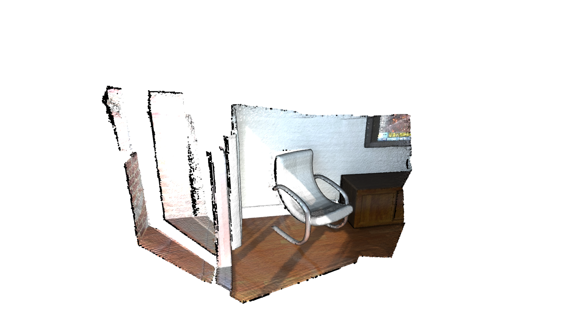
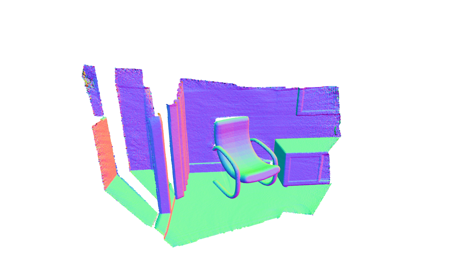
输出:
要更改相机的视场角(Field of View),首先需要获取可视化控制器的实例。要修改视场角,可使用 change_field_of_view。
def custom_draw_geometry_with_custom_fov(pcd, fov_step): vis = o3d.visualization.Visualizer() vis.create_window() vis.add_geometry(pcd) ctr = vis.get_view_control() print("Field of view (before changing) %.2f" % ctr.get_field_of_view()) ctr.change_field_of_view(step=fov_step) print("Field of view (after changing) %.2f" % ctr.get_field_of_view()) vis.run() vis.destroy_window()视场角(FoV)可以被设置在 [5, 90] 度的范围内。请注意,change_field_of_view 会把指定的 FoV 值叠加到当前 FoV 上。默认情况下,可视化器的 FoV 为 60 度。调用如下代码:
custom_draw_geometry_with_custom_fov(pcd, 90.0)会在默认的 60 度之上再叠加指定的 90 度。由于超出了允许的最大 FoV,最终 FoV 会被设置为 90 度。
而如下代码:
custom_draw_geometry_with_custom_fov(pcd, -90.0)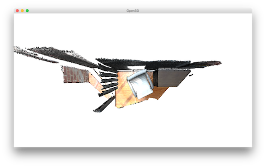
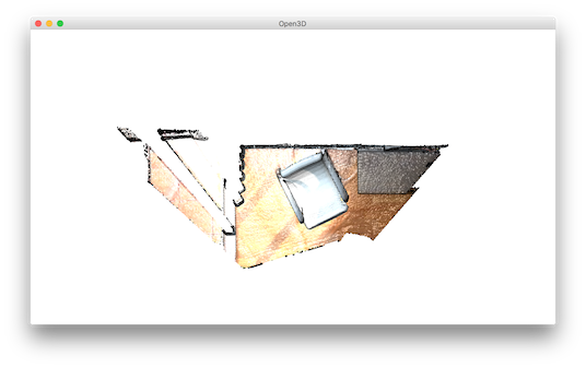
会把 FoV 设置为 5 度,因为 60 - 90 = -30 小于 5 度。
def custom_draw_geometry_with_rotation(pcd):
    def rotate_view(vis):        ctr = vis.get_view_control()        ctr.rotate(10.0, 0.0)        return False
o3d.visualization.draw_geometries_with_animation_callback([pcd], rotate_view)函数 draw_geometries_with_animation_callback 把一个 Python 回调函数 rotate_view 注册为主循环的空闲(idle)函数。每当可视化器处于空闲状态时,它就沿 x 轴旋转视角,由此定义了一种动画行为。
def custom_draw_geometry_with_key_callback(pcd, render_option_path):
    def change_background_to_black(vis):        opt = vis.get_render_option()        opt.background_color = np.asarray([0, 0, 0])        return False
    def load_render_option(vis):        vis.get_render_option().load_from_json(render_option_path)        return False
    def capture_depth(vis):        depth = vis.capture_depth_float_buffer()        plt.imshow(np.asarray(depth))        plt.show()        return False
    def capture_image(vis):        image = vis.capture_screen_float_buffer()        plt.imshow(np.asarray(image))        plt.show()        return False
    key_to_callback = {}    key_to_callback[ord("K")] = change_background_to_black    key_to_callback[ord("R")] = load_render_option    key_to_callback[ord(",")] = capture_depth    key_to_callback[ord(".")] = capture_image    o3d.visualization.draw_geometries_with_key_callbacks([pcd], key_to_callback)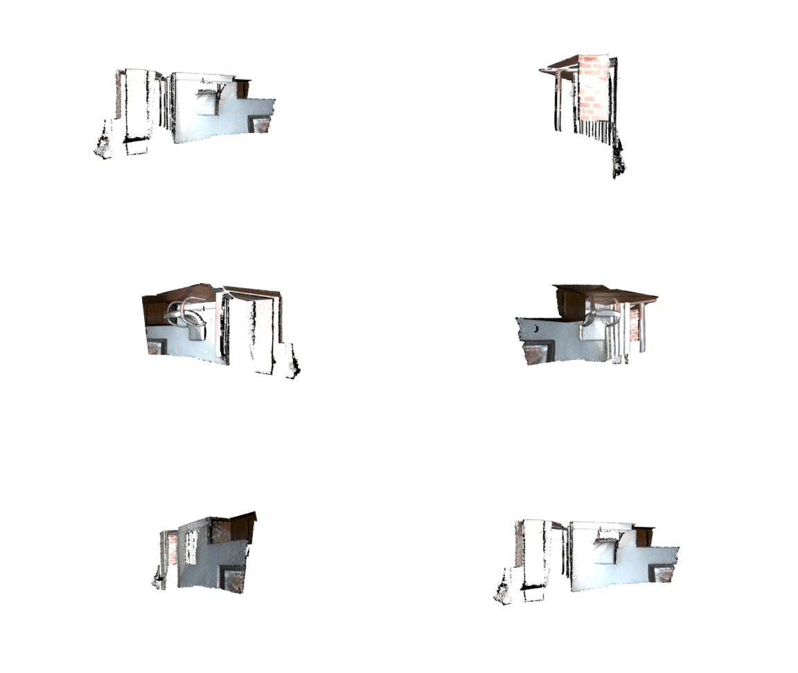
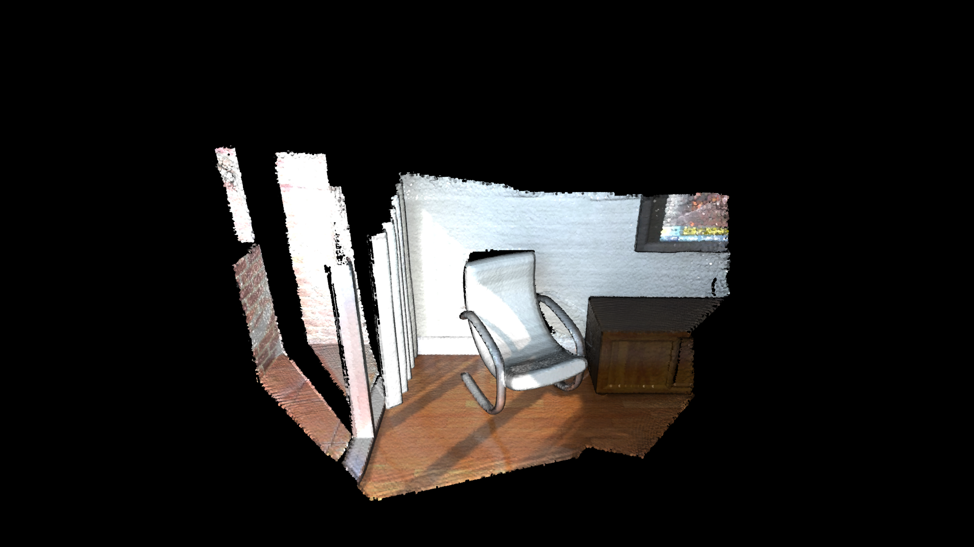
回调函数也可以在按键事件发生时被触发。这个脚本注册了四个按键。例如,按 k 键会把背景色改为黑色。
在自定义动画中捕获图像
Section titled “在自定义动画中捕获图像”def custom_draw_geometry_with_camera_trajectory(pcd, render_option_path, camera_trajectory_path): custom_draw_geometry_with_camera_trajectory.index = -1 custom_draw_geometry_with_camera_trajectory.trajectory = \ o3d.io.read_pinhole_camera_trajectory(camera_trajectory_path) custom_draw_geometry_with_camera_trajectory.vis = o3d.visualization.Visualizer( ) image_path = os.path.join(test_data_path, 'image') if not os.path.exists(image_path): os.makedirs(image_path) depth_path = os.path.join(test_data_path, 'depth') if not os.path.exists(depth_path): os.makedirs(depth_path)
def move_forward(vis): # This function is called within the o3d.visualization.Visualizer::run() loop # The run loop calls the function, then re-render # So the sequence in this function is to: # 1. Capture frame # 2. index++, check ending criteria # 3. Set camera # 4. (Re-render) ctr = vis.get_view_control() glb = custom_draw_geometry_with_camera_trajectory if glb.index >= 0: print("Capture image {:05d}".format(glb.index)) depth = vis.capture_depth_float_buffer(False) image = vis.capture_screen_float_buffer(False) plt.imsave(os.path.join(depth_path, '{:05d}.png'.format(glb.index)), np.asarray(depth), dpi=1) plt.imsave(os.path.join(image_path, '{:05d}.png'.format(glb.index)), np.asarray(image), dpi=1) # vis.capture_depth_image("depth/{:05d}.png".format(glb.index), False) # vis.capture_screen_image("image/{:05d}.png".format(glb.index), False) glb.index = glb.index + 1 if glb.index < len(glb.trajectory.parameters): ctr.convert_from_pinhole_camera_parameters( glb.trajectory.parameters[glb.index], allow_arbitrary=True) else: custom_draw_geometry_with_camera_trajectory.vis. \ register_animation_callback(None) return False
vis = custom_draw_geometry_with_camera_trajectory.vis vis.create_window() vis.add_geometry(pcd) vis.get_render_option().load_from_json(render_option_path) vis.register_animation_callback(move_forward) vis.run() vis.destroy_window()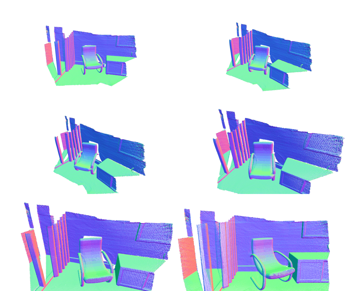
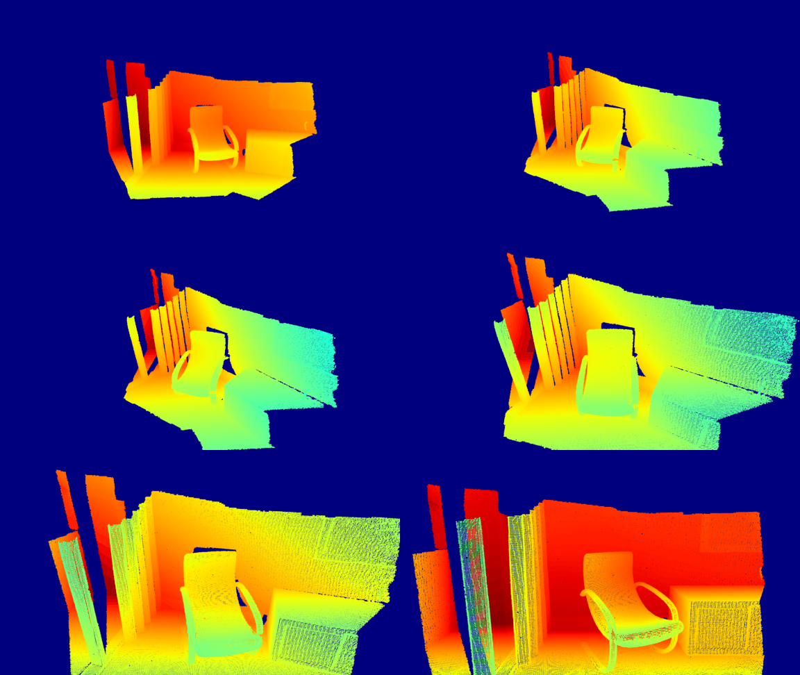
这个函数读取一条相机轨迹,然后定义了一个动画函数 move_forward 来沿相机轨迹行进。在该动画函数中,分别使用 Visualizer.capture_depth_float_buffer 和 Visualizer.capture_screen_float_buffer 捕获彩色图像和深度图像。这些图像会被保存为 PNG 文件。
捕获到的图像序列:
捕获到的深度序列:
为物体应用纹理贴图
Section titled “为物体应用纹理贴图”本示例函数使用渲染类来加载一个物体并为其应用纹理贴图(Texture map)。它可以应用物体目录中存在的任意一种 albedo、normal、ao、metallic 或 roughness 纹理。
这个函数以物体模型目录作为输入,并从中加载该物体。随后它会在目录中查找可用的纹理并将其应用到物体上。在应用纹理之前,必须确保纹理具有 defaultLit 着色器(shader)所支持的预期属性:
- albedo(反照率):必须是 3 通道或 4 通道图像,其中 RGB 分量表示反照率。如果存在第 4 个通道,则它是用于透明度的 alpha 通道。
defaultLit不支持透明度。若要使用透明度,必须改用defaultLitTransparency,它类似于defaultLit,区别在于它使用 alpha 通道来实现透明度。 - normal(法线):必须是 3 通道图像,其中 RGB 分量表示每个像素处切线空间(tangent space)内的法线。
- roughness(粗糙度):可以是 1、2、3 或 4 通道图像。但只有第 1 个通道(红色)被使用,表示适用的粗糙度。取值范围为 0(光滑且高反光)到 1(非常粗糙且漫反射)。
- metallic(金属度):可以是 1、2、3 或 4 通道图像。但只有第 1 个通道(红色)被使用,表示适用的金属质感。取值范围为 0(非金属)到 1(金属)。注意,介于两者之间的数值通常在物理上并不真实。
- ao(环境光遮蔽,Ambient Occlusion):可以是 1、2、3 或 4 通道图像。但只有第 1 个通道(红色)被使用,表示环境光遮蔽。取值范围为 0(表示所有像素都被完全遮蔽、不受间接光照影响)到 1(表示所有像素都被间接光照完全照亮)。
- reflectance(反射率):可以是 1、2、3 或 4 通道图像。但只有第 1 个通道(红色)被使用,表示图像的反射或折射。取值范围为 0(不反射)到 1(高反射)。通常,物理上准确的材质其值不会低于 0.35。
- anisotropy(各向异性):可以是 1、2、3 或 4 通道图像。但只有第 1 个通道(红色)被使用,表示图像的各向异性反射或折射。它用于模拟具有各向异性反射的材质,如拉丝金属。
- ao_rough_metal:必须是 3 通道图像。如果设置了此项,则 roughness、metallic 和 ao 纹理贴图会被忽略;转而使用 ao_rough_metal,其中红色通道为 ao 贴图,绿色通道为 roughness 贴图,蓝色通道为 metallic 贴图。
下面是一段示例 Python 代码:它推导出纹理路径,检查纹理是否可用,然后加载纹理。
import open3d as o3dimport open3d.visualization.gui as guiimport open3d.visualization.rendering as renderingimport sys, os

def main():    if len(sys.argv) < 2:        print("Usage: texture-model.py [model directory]\n\t This example will load [model directory].obj and any of albedo, normal, ao, metallic and roughness textures present.")        exit()
    # Derive the object path set the model, material, and shader    model_dir = sys.argv[1]    model_name = os.path.join(model_dir, os.path.basename(model_dir) + ".obj")    model = o3d.io.read_triangle_mesh(model_name)    material = o3d.visualization.rendering.Material()    material.shader = "defaultLit"
    # Derive the texture paths    albedo_name = os.path.join(model_dir, "albedo.png")    normal_name = os.path.join(model_dir, "normal.png")    ao_name = os.path.join(model_dir, "ao.png")    metallic_name = os.path.join(model_dir, "metallic.png")    roughness_name = os.path.join(model_dir, "roughness.png")
    # Check if the textures are available and loads the texture. For example, if metallic exists then load metallic texture    if os.path.exists(albedo_name):        material.albedo_img = o3d.io.read_image(albedo_name)    if os.path.exists(normal_name):        material.normal_img = o3d.io.read_image(normal_name)    if os.path.exists(ao_name):        material.ao_img = o3d.io.read_image(ao_name)    if os.path.exists(metallic_name):        material.base_metallic = 1.0        material.metallic_img = o3d.io.read_image(metallic_name)    if os.path.exists(roughness_name):        material.roughness_img = o3d.io.read_image(roughness_name)
    # Draw an object named cube using the available model and texture    o3d.visualization.draw([{"name": "cube", "geometry": model, "material": material}])

if __name__ == "__main__":    main()