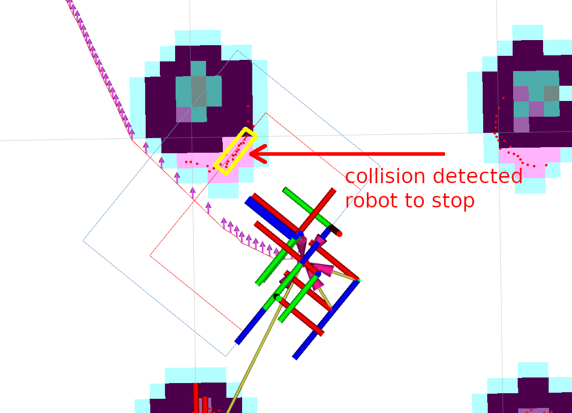
使用碰撞监控器(Collision Monitor)
本教程介绍如何在 Nav2 软件栈中使用碰撞监控器(Collision Monitor),你可以根据自身环境和需求进行相应配置。
假定 ROS 2 和 Nav2 依赖包已安装或在本地构建。 请确保 Nav2 项目也已按照构建说明中的方式在本地构建。
配置碰撞监控器
Section titled “配置碰撞监控器”碰撞监控器(Collision Monitor)节点自带用于演示的 collision_monitor_node.launch.py 启动文件和 collision_monitor_params.yaml 预置参数文件。实际使用时,将其添加到 Nav2 主启动文件中也很简单。
本演示将创建两个多边形区域:一个位于机器人前方内侧的停止(stop)多边形,以及一个较大的减速(slowdown)多边形:
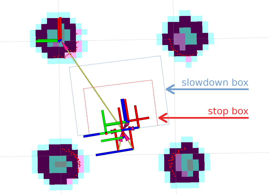
如果减速区域内出现的点多于 3 个,机器人会将速度降至当前值的 30%。
当障碍物靠近机器人达到危险距离时,内侧停止区域将发挥作用。
为此,需要在 collision_monitor_params.yaml 参数文件中添加以下配置。停止多边形命名为 PolygonStop,减速多边形命名为 PolygonSlow:
polygons: ["PolygonStop", "PolygonSlow"]PolygonStop: type: "polygon" points: "[[0.4, 0.3], [0.4, -0.3], [0.0, -0.3], [0.0, 0.3]]" action_type: "stop" min_points: 4 # max_points: 3 for Humble visualize: True polygon_pub_topic: "polygon_stop"PolygonSlow: type: "polygon" points: "[[0.6, 0.4], [0.6, -0.4], [0.0, -0.4], [0.0, 0.4]]" action_type: "slowdown" min_points: 4 # max_points: 3 for Humble slowdown_ratio: 0.3 visualize: True polygon_pub_topic: "polygon_slowdown"注意:也可以使用圆形(circle)替代多边形——例如全向移动机器人,碰撞可能来自任何方向。不过本教程重点介绍多边形配置。同理,此处也不讨论 Approach 模型。两者均可通过参考碰撞监控器配置指南轻松启用。
注意:本教程中的两个多边形均为静态配置。也可以通过话题消息动态调整多边形顶点或足迹(footprint),相关详情请参阅配置指南。
配置生效至少需要添加一个数据源。
本演示使用激光雷达(PointCloud2 以及 Range/Sonar/IR 等传感器也可以使用),碰撞监控器节点的对应配置如下:
observation_sources: ["scan"]scan: type: "scan" topic: "scan"需设置话题名称、frame ID 和超时时间(timeout),使其与默认 Nav2 配置兼容。
此时,完整的 nav2_collision_monitor/params/collision_monitor_params.yaml 文件如下所示:
collision_monitor: ros__parameters: enabled: True base_frame_id: "base_footprint" odom_frame_id: "odom" cmd_vel_in_topic: "cmd_vel_smoothed" cmd_vel_out_topic: "cmd_vel" transform_tolerance: 0.5 source_timeout: 5.0 stop_pub_timeout: 2.0 enable_stamped_cmd_vel: True # False for Jazzy or older by default polygons: ["PolygonStop", "PolygonSlow"] PolygonStop: type: "polygon" points: "[[0.4, 0.3], [0.4, -0.3], [0.0, -0.3], [0.0, 0.3]]" action_type: "stop" min_points: 4 # max_points: 3 for Humble visualize: True polygon_pub_topic: "polygon_stop" PolygonSlow: type: "polygon" points: "[[0.6, 0.4], [0.6, -0.4], [0.0, -0.4], [0.0, 0.4]]" action_type: "slowdown" min_points: 4 # max_points: 3 for Humble slowdown_ratio: 0.3 visualize: True polygon_pub_topic: "polygon_slowdown" observation_sources: ["scan"] scan: type: "scan" topic: "scan"使用 VelocityPolygon 配置碰撞监控器
Section titled “使用 VelocityPolygon 配置碰撞监控器”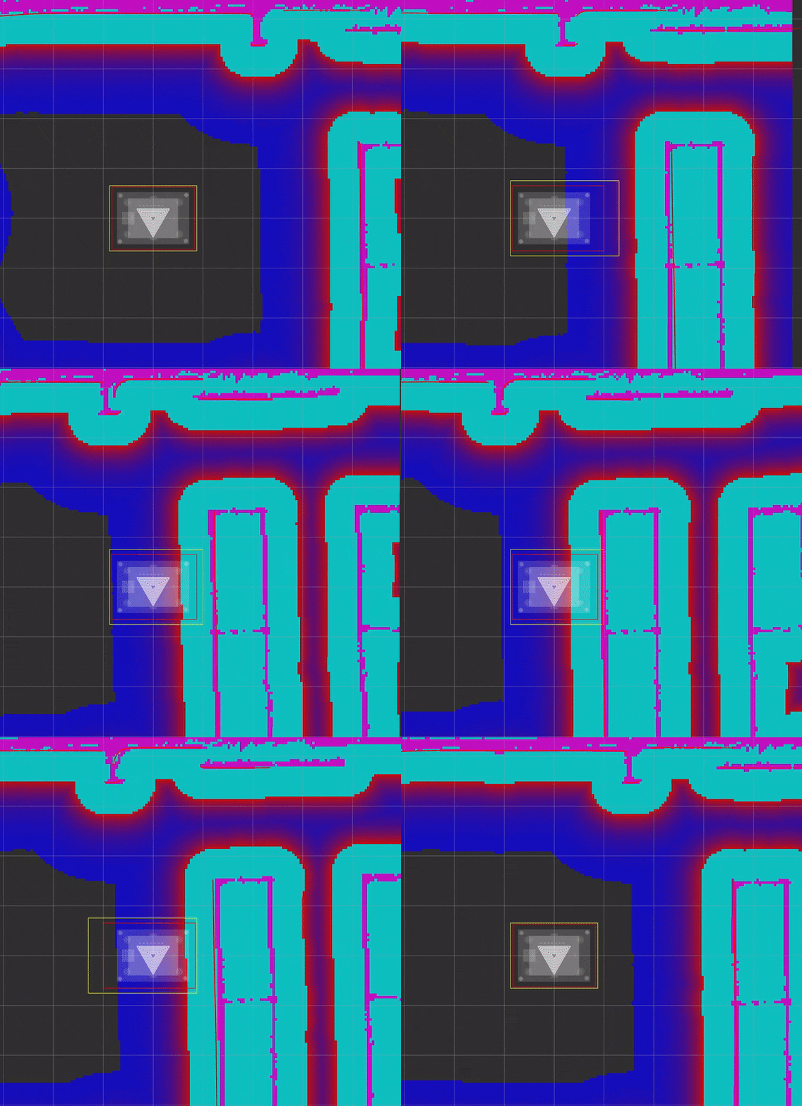
本部分教程将配置碰撞监控器使用 VelocityPolygon 类型来执行 stop(停止)动作。VelocityPolygon 允许设置多个多边形,以覆盖机器人不同的速度范围。例如,可以为旋转、前进或后退分别配置不同的多边形。碰撞监控器会将机器人当前速度与每个子多边形进行比对,从而确定用于碰撞检测的合适多边形。
一般来说,使用 VelocityPolygon 类型配置碰撞监控器的步骤如下:
- 在
polygons参数列表中添加一个VelocityPolygon - 配置该
VelocityPolygon - 指定多边形的
holonomic属性(默认为false) - 首先在
velocity_polygons列表中添加一个stopped子多边形,覆盖机器人速度的完整范围 - 在
velocity_polygons列表前部添加更多子多边形,为每种运动类型(如旋转、前进、后退)覆盖对应的机器人速度范围
本示例考虑一台**非全向(non-holonomic)**机器人,线速度极限为 -1.0 至 1.0 m/s,角速度极限为 -1.0 至 1.0 rad/s。子多边形的 linear_min 和 linear_max 参数应设置为机器人的线速度极限,theta_min 和 theta_max 参数应设置为机器人的角速度极限。
下面是使用 4 个子多边形覆盖机器人全部速度极限范围的示例配置:
polygons: ["VelocityPolygonStop"]VelocityPolygonStop: type: "velocity_polygon" action_type: "stop" min_points: 6 visualize: True enabled: True polygon_pub_topic: "velocity_polygon_stop" velocity_polygons: ["rotation", "translation_forward", "translation_backward", "stopped"] holonomic: false rotation: points: "[[0.3, 0.3], [0.3, -0.3], [-0.3, -0.3], [-0.3, 0.3]]" linear_min: 0.0 linear_max: 0.05 theta_min: -1.0 theta_max: 1.0 translation_forward: points: "[[0.35, 0.3], [0.35, -0.3], [-0.2, -0.3], [-0.2, 0.3]]" linear_min: 0.0 linear_max: 1.0 theta_min: -1.0 theta_max: 1.0 translation_backward: points: "[[0.2, 0.3], [0.2, -0.3], [-0.35, -0.3], [-0.35, 0.3]]" linear_min: -1.0 linear_max: 0.0 theta_min: -1.0 theta_max: 1.0 # This is the last polygon to be checked, it should cover the entire range of robot's velocities # It is used as the stopped polygon when the robot is not moving and as a fallback if the velocity # is not covered by any of the other sub-polygons stopped: points: "[[0.25, 0.25], [0.25, -0.25], [-0.25, -0.25], [-0.25, 0.25]]" linear_min: -1.0 linear_max: 1.0 theta_min: -1.0 theta_max: 1.0注意:建议将
stopped子多边形作为velocity_polygons列表的最后一项,以覆盖机器人速度的整个范围。当速度不在任何子多边形范围内时,碰撞监控器会输出一条警告消息,并继续使用先前匹配的多边形。
注意:当速度同时被多个子多边形覆盖时,将使用列表中的第一个子多边形。
对于全向(holonomic)机器人:
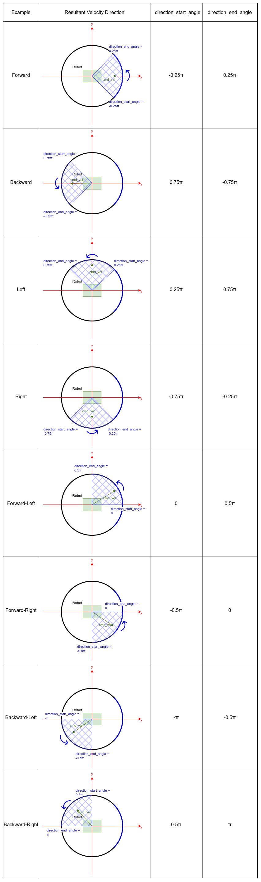
对于全向(holonomic)机器人,应将 holonomic 属性设置为 true。此时 linear_min 和 linear_max 参数应覆盖机器人合速度幅值的极限(仅使用非负值),theta_min 和 theta_max 参数应覆盖机器人的角速度极限。此外还有 direction_start_angle 和 direction_end_angle 两个参数,用于指定合速度的方向。所覆盖的方向始终以逆时针方向从 direction_start_angle 跨越到 direction_end_angle。
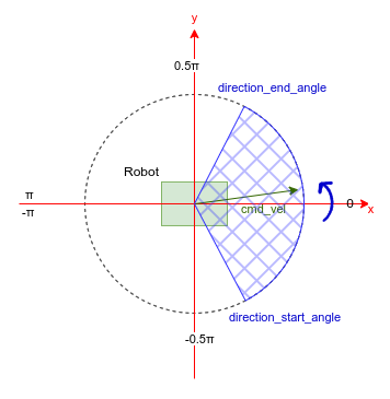
下面展示了几种全向机器人的常见配置,覆盖合速度的多个方向:
collision_monitor:  ros__parameters:    base_frame_id: "base_footprint"    odom_frame_id: "odom"    cmd_vel_in_topic: "cmd_vel_smoothed"    cmd_vel_out_topic: "nav_vel"    state_topic: "collision_monitor_state"    transform_tolerance: 0.3    source_timeout: 1.0    base_shift_correction: True    stop_pub_timeout: 2.0    holonomic: true       # Set to true for holonomic robots
    polygons: ["VelocityPolygonSlow"]
    VelocityPolygonSlow:      type: "velocity_polygon"      action_type: "slowdown"      slowdown_ratio: 0.5      holonomic: true      visualize: True      enabled: True      velocity_polygons: [        "forward", "forward_left", "left", "backward_left",        "backward", "backward_right", "right", "forward_right",        "stopped"      ]
      forward:        points: "[[0.6, 0.4], [0.6, -0.4], [-0.3, -0.4], [-0.3, 0.4]]"        linear_min: 0.05        linear_max: 1.0        direction_start_angle: -0.785   # -0.25pi        direction_end_angle: 0.785      # 0.25pi        theta_min: -1.0        theta_max: 1.0
      forward_left:        points: "[[0.55, 0.55], [0.55, -0.3], [-0.3, -0.3], [-0.3, 0.55]]"        linear_min: 0.05        linear_max: 1.0        direction_start_angle: 0.0      # 0.0pi        direction_end_angle: 1.571      # 0.5pi        theta_min: -1.0        theta_max: 1.0
      left:        points: "[[0.4, 0.6], [0.4, -0.4], [-0.4, -0.4], [-0.4, 0.6]]"        linear_min: 0.05        linear_max: 1.0        direction_start_angle: 0.785     # 0.25pi        direction_end_angle: 2.356       # 0.75pi        theta_min: -1.0        theta_max: 1.0
      backward_left:        points: "[[0.3, 0.55], [0.3, -0.3], [-0.55, -0.3], [-0.55, 0.55]]"        linear_min: 0.05        linear_max: 1.0        direction_start_angle: -3.1415   # -pi        direction_end_angle: -1.571      # -0.5pi        theta_min: -1.0        theta_max: 1.0
      backward:        points: "[[0.3, 0.4], [0.3, -0.4], [-0.6, -0.4], [-0.6, 0.4]]"        linear_min: 0.05        linear_max: 1.0        direction_start_angle: 2.356     # 0.75pi        direction_end_angle: -2.356      # -0.75pi        theta_min: -1.0        theta_max: 1.0
      backward_right:        points: "[[0.3, 0.3], [0.3, -0.55], [-0.55, -0.55], [-0.55, 0.3]]"        linear_min: 0.05        linear_max: 1.0        direction_start_angle: 1.571     # 0.5pi        direction_end_angle: 3.1415      # pi        theta_min: -1.0        theta_max: 1.0
      right:        points: "[[0.4, 0.4], [0.4, -0.6], [-0.4, -0.6], [-0.4, 0.4]]"        linear_min: 0.05        linear_max: 1.0        direction_start_angle: -2.356    # -0.75pi        direction_end_angle: -0.785      # -0.25pi        theta_min: -1.0        theta_max: 1.0
      forward_right:        points: "[[0.55, 0.3], [0.55, -0.55], [-0.3, -0.55], [-0.3, 0.3]]"        linear_min: 0.05        linear_max: 1.0        direction_start_angle: -1.571   # -0.5pi        direction_end_angle: 0.0        # 0.0pi        theta_min: -1.0        theta_max: 1.0
      # Stopped      stopped:        points: "[[0.4, 0.4], [0.4, -0.4], [-0.4, -0.4], [-0.4, 0.4]]"        linear_min: 0.0        linear_max: 0.05        direction_start_angle: -3.1415        direction_end_angle: 3.1415        theta_min: -1.0        theta_max: 1.0
准备 Nav2 软件栈
Section titled “准备 Nav2 软件栈”碰撞监控器设计为在 Nav2 之下运行的独立安全节点。
它充当控制器发出的 cmd_vel 消息的过滤器,用于避免潜在碰撞。
如果没有触发任何区域,则原样输出 cmd_vel 消息。
否则,它会按需对速度进行缩放或置零停止。
默认情况下,碰撞监控器配置为与 Nav2 bringup 包配合使用,与 navigation_launch.py 启动文件并行运行。要使碰撞监控器与速度平滑器(Velocity Smoother)正确配合工作,需按如下方式移除 navigation_launch.py 启动脚本中速度平滑器的 cmd_vel_smoothed 重映射。这样速度平滑器的输出话题将保持不变,而该话题正是新添加的碰撞监控器的输入:
Node( package='nav2_velocity_smoother', executable='velocity_smoother', name='velocity_smoother', output='screen', respawn=use_respawn, respawn_delay=2.0, parameters=[configured_params], arguments=['--ros-args', '--log-level', log_level], remappings=remappings +- [('cmd_vel', 'cmd_vel_nav'), ('cmd_vel_smoothed', 'cmd_vel')]),+ [('cmd_vel', 'cmd_vel_nav')]),...ComposableNode( package='nav2_velocity_smoother', plugin='nav2_velocity_smoother::VelocitySmoother', name='velocity_smoother', parameters=[configured_params], remappings=remappings +- [('cmd_vel', 'cmd_vel_nav'), ('cmd_vel_smoothed', 'cmd_vel')]),+ [('cmd_vel', 'cmd_vel_nav')]),如果你更改了碰撞监控器默认的 cmd_vel_in_topic 和 cmd_vel_out_topic 配置,请确保速度平滑器的默认输出话题 cmd_vel_smoothed 与碰撞监控器的 cmd_vel_in_topic 参数值一致。同时,碰撞监控器的 cmd_vel_out_topic 参数值应指向实际的 cmd_vel 话题,以完成速度消息的最终输出。
注意:碰撞监控器作为安全节点,必须是速度消息后处理链中的最后一环,即最终向
cmd_vel话题发布消息的节点。它可以位于速度平滑器之后(如本演示所示),也可以位于控制器服务器(Controller Server)输出的未经平滑处理的速度之后(例如系统中未启用速度平滑器时),或者位于自定义配置中产生最终速度的任何其他模块之后。因此,在任何自定义 Nav2 启动配置中,最后一个向cmd_vel话题发布消息的节点都应重映射为向碰撞监控器的输入话题(由 ROS 参数cmd_vel_in_topic配置,默认为cmd_vel_smoothed)发布消息。
碰撞监控器节点调优完成、cmd_vel 话题调整妥当后,即可运行碰撞监控器。
请按照快速入门中的说明运行 Nav2 软件栈:
ros2 launch nav2_bringup tb3_simulation_launch.py headless:=False在另一个控制台中,使用其启动文件启动碰撞监控器节点:
ros2 launch nav2_collision_monitor collision_monitor_node.launch.py由于 PolygonStop 和 PolygonSlow 两个多边形都有各自的发布者,可以将它们添加到可视化中,如下图所示:
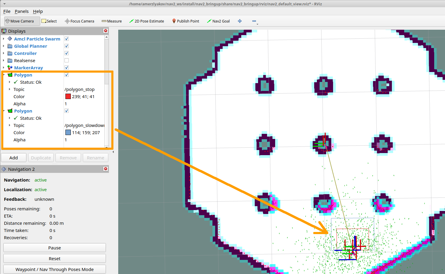
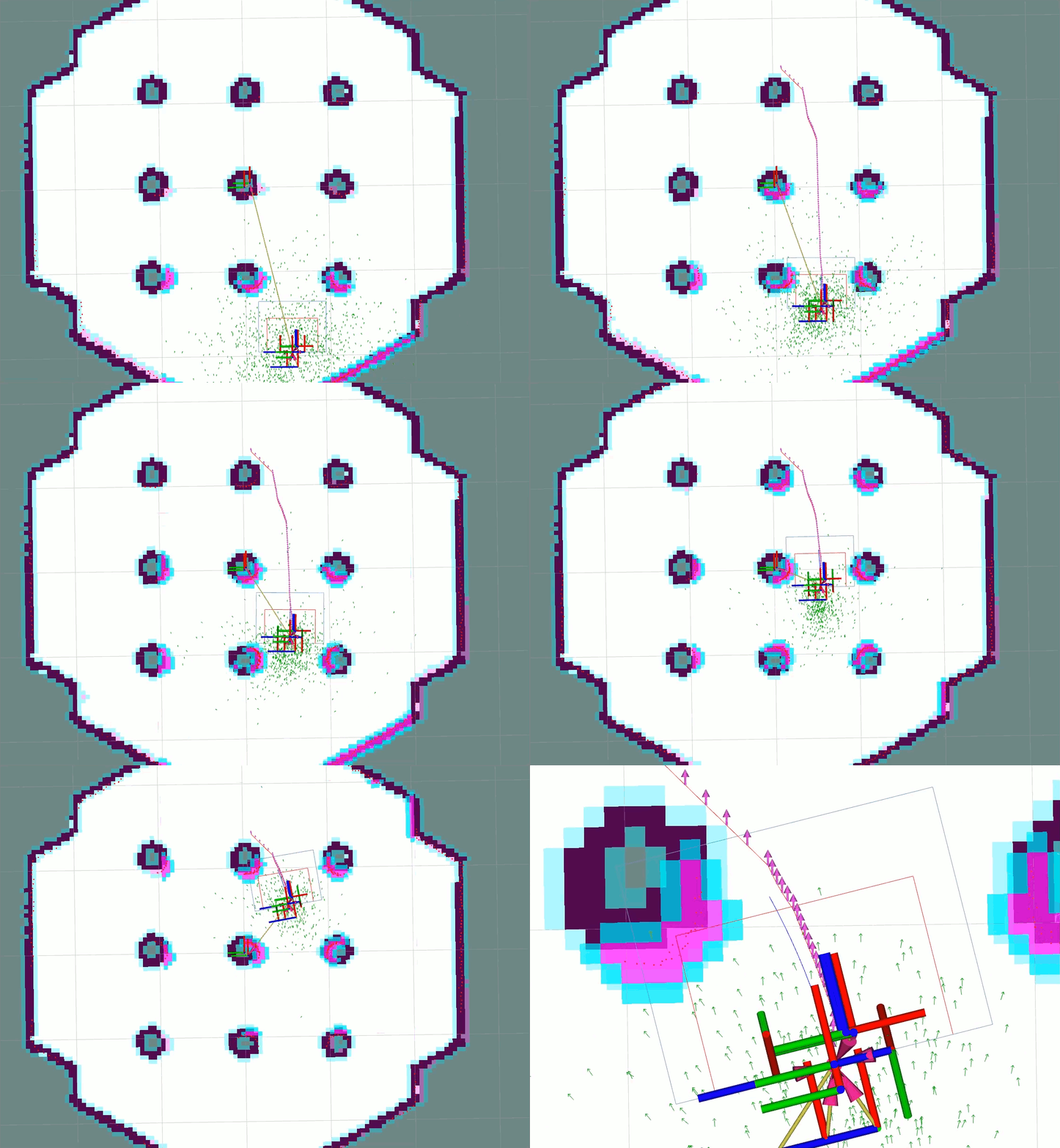
设置初始位姿(initial pose),然后在地图上设定 Nav2 目标点。 机器人将开始移动,接近障碍物时减速,并在非常靠近时停下: