
Gazebo 传感器设置
本指南介绍传感器在安全导航中的重要性,以及如何为 Nav2 配置传感器。前半部分简要介绍 Nav2 中常用的传感器及常见传感器消息类型,然后在此前构建的仿真机器人 sam_bot 上添加基本传感器,并在 RViz 中可视化验证仿真传感器数据。
传感器读数可用于建图、定位和感知。后半部分讨论建图与定位如何使用传感器数据,并介绍 Nav2 的 nav2_costmap_2d 包——它生成路径规划所需的代价地图(costmap)。下面为该包配置基本参数,使其正确接收 sam_bot 的传感器数据,最后在 RViz 中可视化生成的代价地图以验证结果。
移动机器人配备大量传感器来感知周围环境。传感器数据可用于构建和维护环境地图、在地图上定位机器人,以及检测环境中的障碍物——这些任务对于在动态环境中安全高效地导航至关重要。
常用传感器包括激光雷达、雷达、RGB 相机、深度相机、IMU 和 GPS。为统一传感器消息格式、方便不同厂商产品互操作,ROS 提供了 sensor_msgs 包来定义标准传感器接口。只要传感器遵循 sensor_msgs 标准,就可以自由选用不同厂商的产品。下一小节将介绍导航中常用的消息类型:sensor_msgs/LaserScan、sensor_msgs/PointCloud2、sensor_msgs/Range 和 sensor_msgs/Image。
除 sensor_msgs 外,还有 radar_msgs 和 vision_msgs 标准接口。radar_msgs 定义了雷达专用消息,vision_msgs 定义了计算机视觉相关消息,如目标检测、分割等机器学习任务的输出。支持的消息包括 vision_msgs/Classification2D、vision_msgs/Classification3D、vision_msgs/Detection2D 和 vision_msgs/Detection3D 等。
注意:更多详情请参阅 sensor_msgs、radar_msgs 和 vision_msgs 的 API 文档。
实体机器人的传感器通常都有对应的 ROS 驱动程序(即连接传感器、将数据填充到消息并发布的 ROS 节点),遵循 sensor_msgs 标准接口。借助这一标准,用户可轻松搭配不同厂商的传感器,Nav2 等通用软件包也能读取这些标准化消息,执行与具体硬件无关的任务。在 sam_bot 等仿真机器人中,Gazebo 的传感器插件同样按照 sensor_msgs 格式发布数据。
常见传感器消息
Section titled “常见传感器消息”本小节介绍设置 Nav2 时常见的几种 sensor_msgs 类型,分别给出简要说明、Gazebo 仿真截图以及 RViz 中的读数可视化。
注意:除下面列出的类型外,还有其他
sensor_msgs类型。完整的消息列表及定义请参阅 sensor_msgs 文档。
sensor_msgs/LaserScan
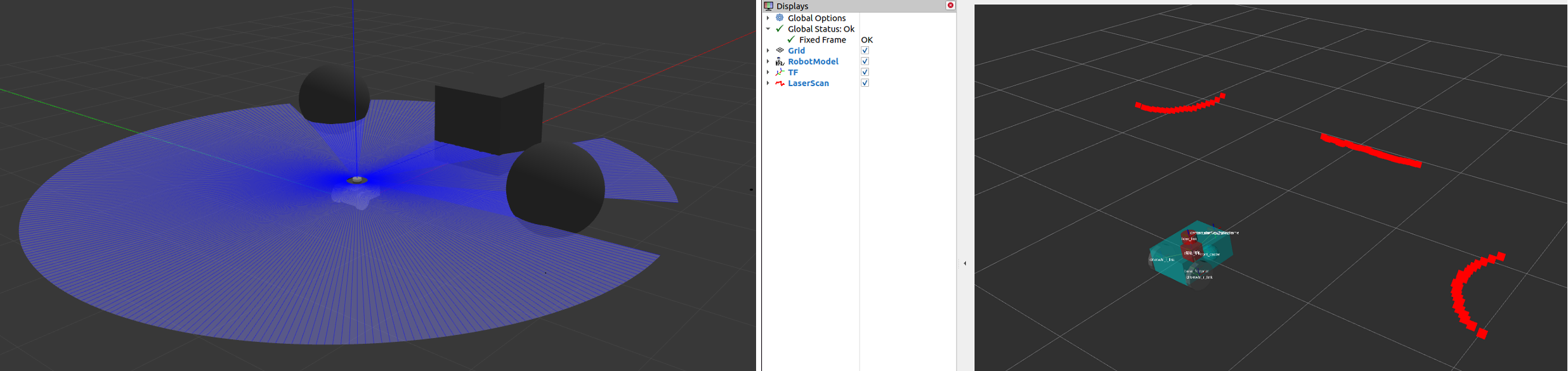
Section titled “sensor_msgs/LaserScan”该消息表示平面激光测距仪的单次扫描,用于 slam_toolbox 和 nav2_amcl 的定位与建图,或 nav2_costmap_2d 的感知。
sensor_msgs/PointCloud2
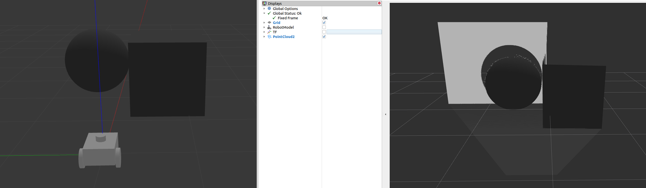
Section titled “sensor_msgs/PointCloud2”该消息包含一组 3D 点及每个点的可选附加信息,数据来源可以是 3D 激光雷达、2D 激光雷达、深度相机等。
sensor_msgs/Range
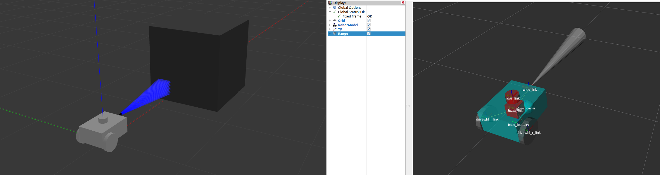
Section titled “sensor_msgs/Range”该消息来自有源测距仪的单次距离读数。测距仪发射能量并报告沿一段弧线有效的单个距离值。声呐、红外传感器和一维测距仪都是使用该消息的典型传感器。
sensor_msgs/Image
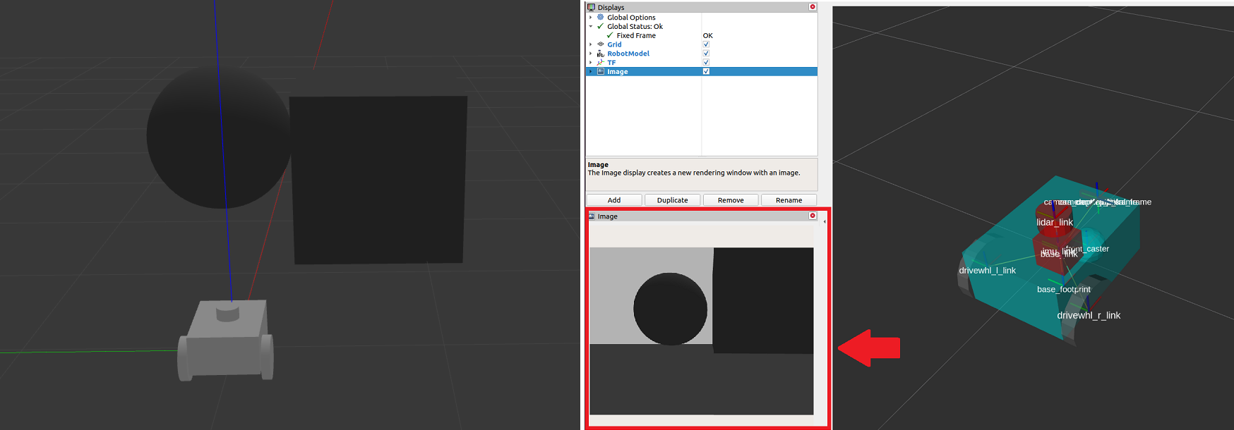
Section titled “sensor_msgs/Image”该消息表示来自 RGB 或深度相机的读数,分别对应 RGB 值或距离值。
使用 Gazebo 仿真传感器
Section titled “使用 Gazebo 仿真传感器”本节以上一个教程为基础,为仿真机器人 sam_bot 添加传感器。与上一个教程中使用 Gazebo 插件添加里程计类似,这里用 Gazebo 插件在 sam_bot 上仿真一个激光雷达和一个深度相机。如果使用的是真实机器人,以下步骤中大部分对于设置 URDF 坐标系仍然必要,提前添加 Gazebo 插件也方便后续使用。
请确保已正确安装 Gazebo,安装步骤可参考上一个教程中的设置与先决条件。
向 URDF 或 SDF 添加 Gazebo 插件
Section titled “向 URDF 或 SDF 添加 Gazebo 插件”首先为 sam_bot 添加激光雷达。在 URDF 的 </robot> 标签前粘贴以下内容,添加激光雷达的连杆和关节:
<link name="lidar_link">  <inertial>    <origin xyz="0 0 0" rpy="0 0 0"/>    <mass value="0.125"/>    <inertia ixx="0.001" ixy="0" ixz="0" iyy="0.001" iyz="0" izz="0.001" />  </inertial>
  <collision>    <origin xyz="0 0 0" rpy="0 0 0"/>    <geometry>      <cylinder radius="0.0508" length="0.055"/>    </geometry>  </collision>
  <visual>    <origin xyz="0 0 0" rpy="0 0 0"/>    <geometry>      <cylinder radius="0.0508" length="0.055"/>    </geometry>  </visual></link>
<joint name="lidar_joint" type="fixed">  <parent link="base_link"/>  <child link="lidar_link"/>  <origin xyz="0 0 0.12" rpy="0 0 0"/></joint>
在 SDF 的 </model> 行前添加以下内容,包含激光雷达的连杆、关节及 Gazebo 传感器配置:
<joint name="lidar_joint" type="fixed">  <parent>base_link</parent>  <child>lidar_link</child>  <pose relative_to="base_link">0.0 0.0 0.12 0 0 0</pose></joint>
<link name='lidar_link'>  <pose relative_to="lidar_joint"/>  <visual name="lidar_link_visual">    <geometry>      <cylinder>        <radius>0.0508</radius>        <length>0.055</length>      </cylinder>    </geometry>  </visual>
  <collision name="lidar_link_collision">    <geometry>      <cylinder>        <radius>0.0508</radius>        <length>0.055</length>      </cylinder>    </geometry>  </collision>
  <xacro:cylinder_inertia m="0.125" r="0.0508" h="0.055"/>
  <sensor name="lidar" type="gpu_lidar">    <always_on>true</always_on>    <visualize>true</visualize>    <update_rate>5</update_rate>    <topic>scan</topic>    <gz_frame_id>lidar_link</gz_frame_id>    <lidar>      <scan>        <horizontal>          <samples>360</samples>          <resolution>1.000000</resolution>          <min_angle>0.000000</min_angle>          <max_angle>6.280000</max_angle>        </horizontal>      </scan>      <range>        <min>0.120000</min>        <max>3.5</max>        <resolution>0.015000</resolution>      </range>      <noise>        <type>gaussian</type>        <mean>0.0</mean>        <stddev>0.01</stddev>      </noise>    </lidar>  </sensor></link>
上面的代码片段为 lidar_link 配置了仿真激光雷达的扫描范围和距离参数,并指定 /scan 作为发布 sensor_msgs/LaserScan 消息的话题。
接下来为 sam_bot 添加深度相机。在 URDF 中激光雷达的 </joint> 标签之后粘贴以下内容,添加相机的连杆和关节:
<link name="camera_link">  <visual>    <origin xyz="0 0 0" rpy="0 0 0"/>    <geometry>      <box size="0.015 0.130 0.022"/>    </geometry>  </visual>
  <collision>    <origin xyz="0 0 0" rpy="0 0 0"/>    <geometry>      <box size="0.015 0.130 0.022"/>    </geometry>  </collision>
  <inertial>    <origin xyz="0 0 0" rpy="0 0 0"/>    <mass value="0.035"/>    <inertia ixx="0.001" ixy="0" ixz="0" iyy="0.001" iyz="0" izz="0.001" />  </inertial></link>
<joint name="camera_joint" type="fixed">  <parent link="base_link"/>  <child link="camera_link"/>  <origin xyz="0.215 0 0.05" rpy="0 0 0"/></joint>
在 SDF 中激光雷达的 </link> 标签之后粘贴以下内容,添加相机的连杆、关节及 Gazebo 传感器配置:
<joint name="camera_joint" type="fixed">  <parent>base_link</parent>  <child>camera_link</child>  <pose relative_to="base_link">0.215 0 0.05 0 0 0</pose></joint>
<link name='camera_link'>  <pose relative_to="camera_joint"/>  <visual name="camera_link_visual">    <geometry>      <box><size>        0.015 0.130 0.0222      </size></box>    </geometry>  </visual>
  <collision name="camera_link_collision">    <geometry>      <box><size>        0.015 0.130 0.0222      </size></box>    </geometry>  </collision>
  <xacro:box_inertia m="0.035" w="0.015" d="0.130" h="0.0222"/>
  <sensor name="depth_camera" type="rgbd_camera">    <always_on>true</always_on>    <visualize>true</visualize>    <update_rate>5.0</update_rate>    <topic>depth_camera</topic>    <gz_frame_id>camera_link</gz_frame_id>    <camera>      <horizontal_fov>1.047198</horizontal_fov>      <image>        <width>640</width>        <height>480</height>      </image>      <clip>        <near>0.05</near>        <far>3</far>      </clip>    </camera>    <baseline>0.2</baseline>    <pointCloudCutoff>0.5</pointCloudCutoff>    <pointCloudCutoffMax>3.0</pointCloudCutoffMax>    <distortionK1>0</distortionK1>    <distortionK2>0</distortionK2>    <distortionK3>0</distortionK3>    <distortionT1>0</distortionT1>    <distortionT2>0</distortionT2>    <CxPrime>0</CxPrime>    <Cx>0</Cx>    <Cy>0</Cy>    <focalLength>0</focalLength>    <hackBaseline>0</hackBaseline>  </sensor></link>
上面的代码片段为 camera_link 配置了仿真深度相机参数,并指定传感器分别向 /depth_camera/image_raw 和 /depth_camera/points 话题发布 sensor_msgs/Image 和 sensor_msgs/PointCloud2 消息。
更新桥接配置
Section titled “更新桥接配置”还需将所需传感器话题从 Gazebo 桥接到 ROS,在 bridge_config.yaml 中添加以下内容:
- ros_topic_name: "/scan"  gz_topic_name: "/scan"  ros_type_name: "sensor_msgs/msg/LaserScan"  gz_type_name: "gz.msgs.LaserScan"  direction: GZ_TO_ROS
- ros_topic_name: "/scan/points"  gz_topic_name: "/scan/points"  ros_type_name: "sensor_msgs/msg/PointCloud2"  gz_type_name: "gz.msgs.PointCloudPacked"  direction: GZ_TO_ROS
- ros_topic_name: "/depth_camera/camera_info"  gz_topic_name: "/depth_camera/camera_info"  ros_type_name: "sensor_msgs/msg/CameraInfo"  gz_type_name: "gz.msgs.CameraInfo"  direction: GZ_TO_ROS
- ros_topic_name: "/depth_camera/points"  gz_topic_name: "/depth_camera/points"  ros_type_name: "sensor_msgs/msg/PointCloud2"  gz_type_name: "gz.msgs.PointCloudPacked"  direction: GZ_TO_ROS
 - ros_topic_name: "/depth_camera/image_raw"   gz_topic_name: "/depth_camera/image"   ros_type_name: "sensor_msgs/msg/Image"   gz_type_name: "gz.msgs.Image"   direction: GZ_TO_ROS
构建、运行与验证
Section titled “构建、运行与验证”现在构建并运行项目。进入项目根目录,执行以下命令:
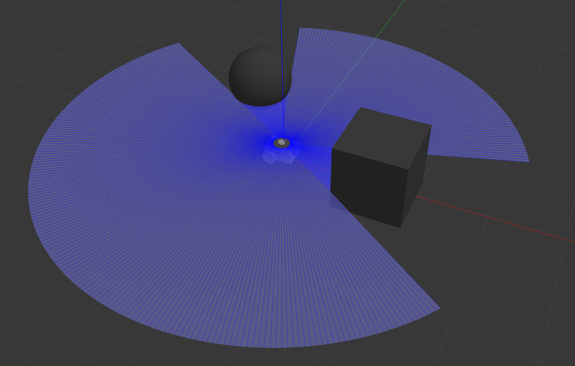
colcon build. install/setup.bashros2 launch sam_bot_description display.launch.pyRViz 和 Gazebo 随即启动,sam_bot 将同时出现在两者中。Gazebo 窗口会加载已创建的世界,sam_bot 在其中生成。此时可看到带有 360 度激光雷达和深度相机的 sam_bot,如下图所示。
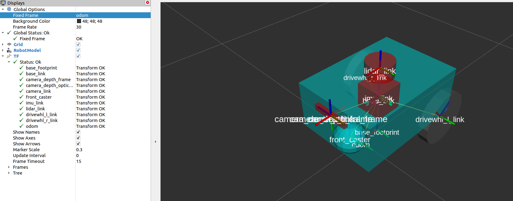
在 RViz 窗口中可验证传感器建模是否正确,以及新添加传感器的坐标变换是否正确:
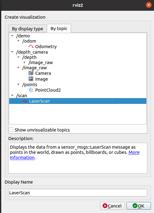
还可以在 RViz 中可视化传感器读数。要可视化 /scan 话题上的 sensor_msgs/LaserScan 消息,点击 RViz 窗口底部的 Add 按钮,切换到 By topic 选项卡,在 /scan 下选择 LaserScan,如下图所示。
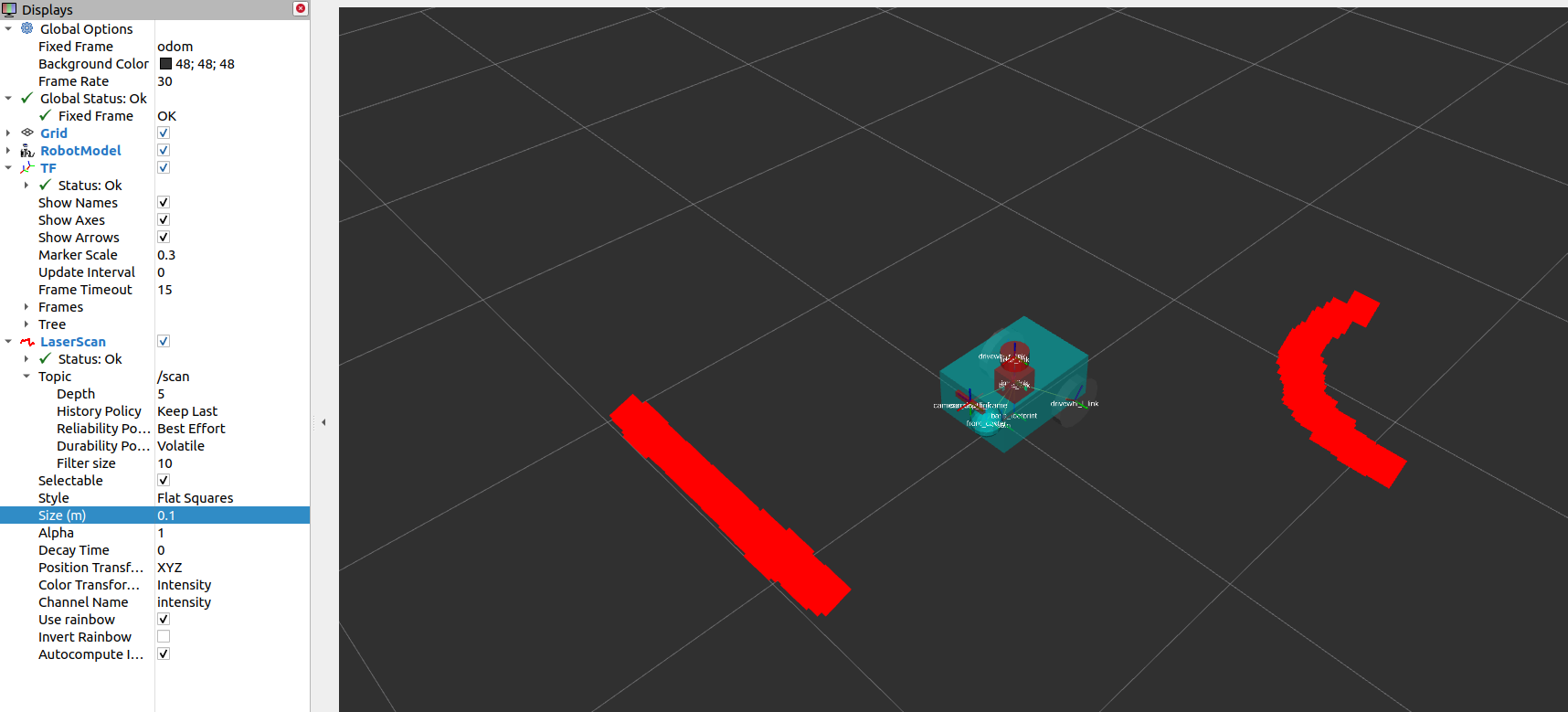
然后将 RViz 中的 Reliability Policy 设为 Best Effort,size 设为 0.1,以便更清晰地观察点云。此时应能看到如下所示的 LaserScan 可视化结果,对应的是添加到 Gazebo 世界中的立方体和球体。
可视化 sensor_msgs/Image 和 sensor_msgs/PointCloud2 的方式相同,分别对 /depth_camera/image_raw 和 /depth_camera/points 话题执行上述操作:
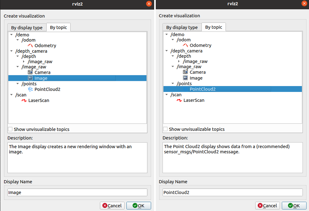
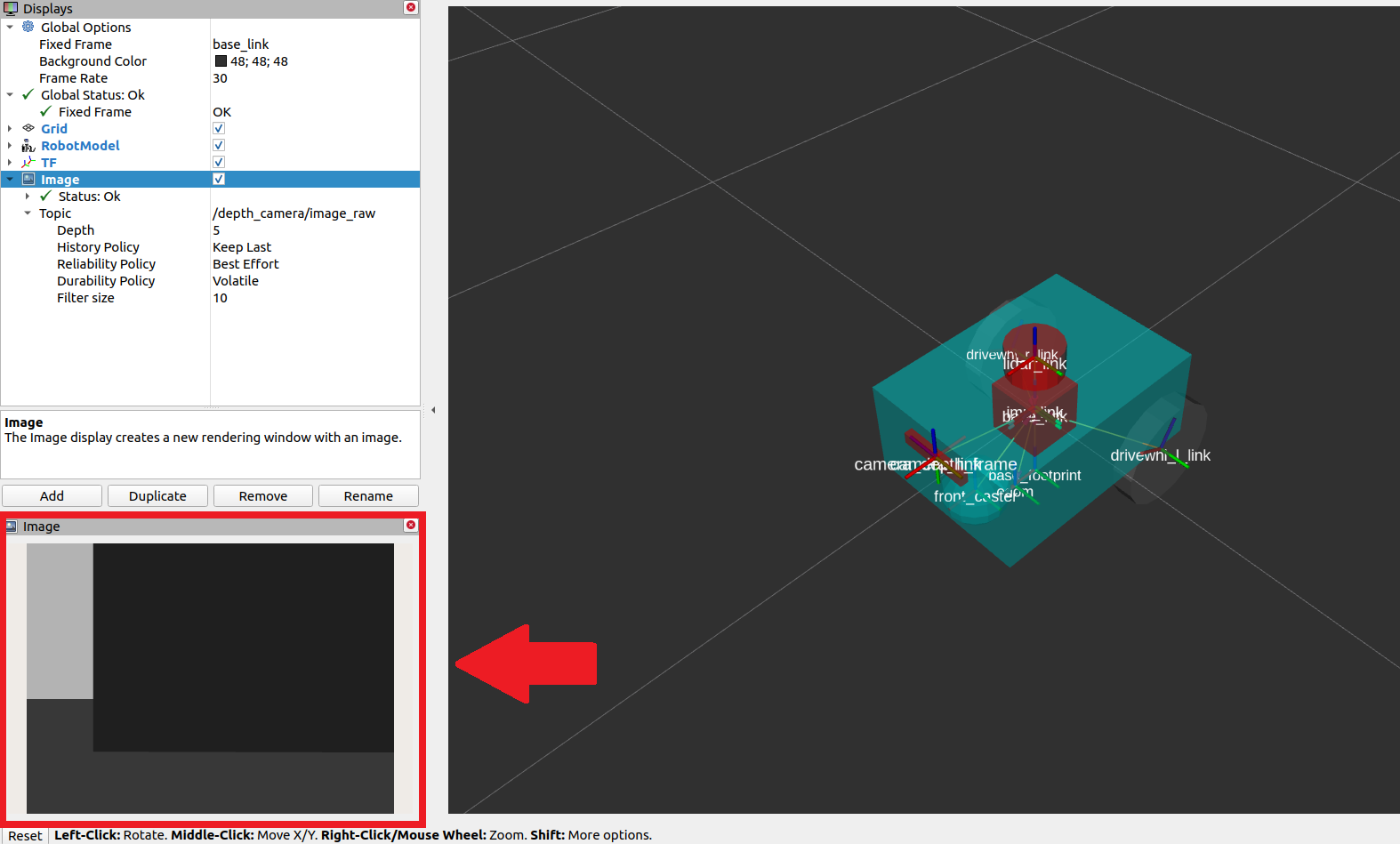
在 RViz 中添加 /depth_camera/image_raw 话题后,将 Reliability Policy 设为 Best Effort,即可在 RViz 左下方的图像窗口中看到立方体画面,如下图所示。
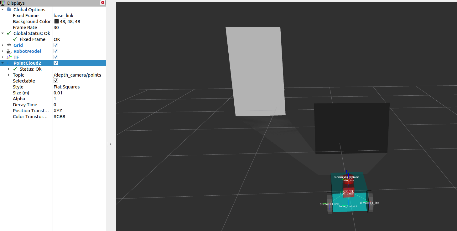
同样,sensor_msgs/PointCloud2 的可视化效果如下所示。
本指南介绍了 Nav2 中常见的传感器消息类型——它们统一了不同厂商传感器的消息格式,并演示了如何使用 Gazebo 为仿真机器人添加传感器,以及如何通过 RViz 验证传感器是否正常工作。